Goal
TIP: Click on pictures in the instructions to see a larger version. Right-click and select ‘Open link in new Tab’ to see the full size image.
| By the end of this section, you will have assembled the base of the printer. |
 |
Tower assembly
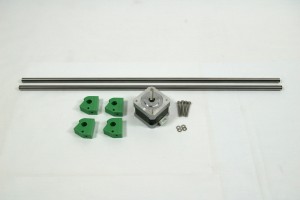
There are three towers, that support the three moving arms of the printer. You will need the following parts:
| # |
Component |
Qty |
Type |
| 934 |
Smooth rod 8mm x 426mm |
2 |
Hardware |
| 408 |
NEMA 17 stepper motor |
1 |
Hardware |
| 1305 |
Motor bracket |
4 |
Printed |
| 112 |
M3x25mm cap head screw |
4 |
Fastener |
| 212 |
M3 plain washer |
8 |
Fastener |
|
 |
TIP: There’s a list of the Fisher 1 printed parts on
THIS PAGE. Click on the ‘Location’, to see a preview of the printed part, if you’re not sure what it is.
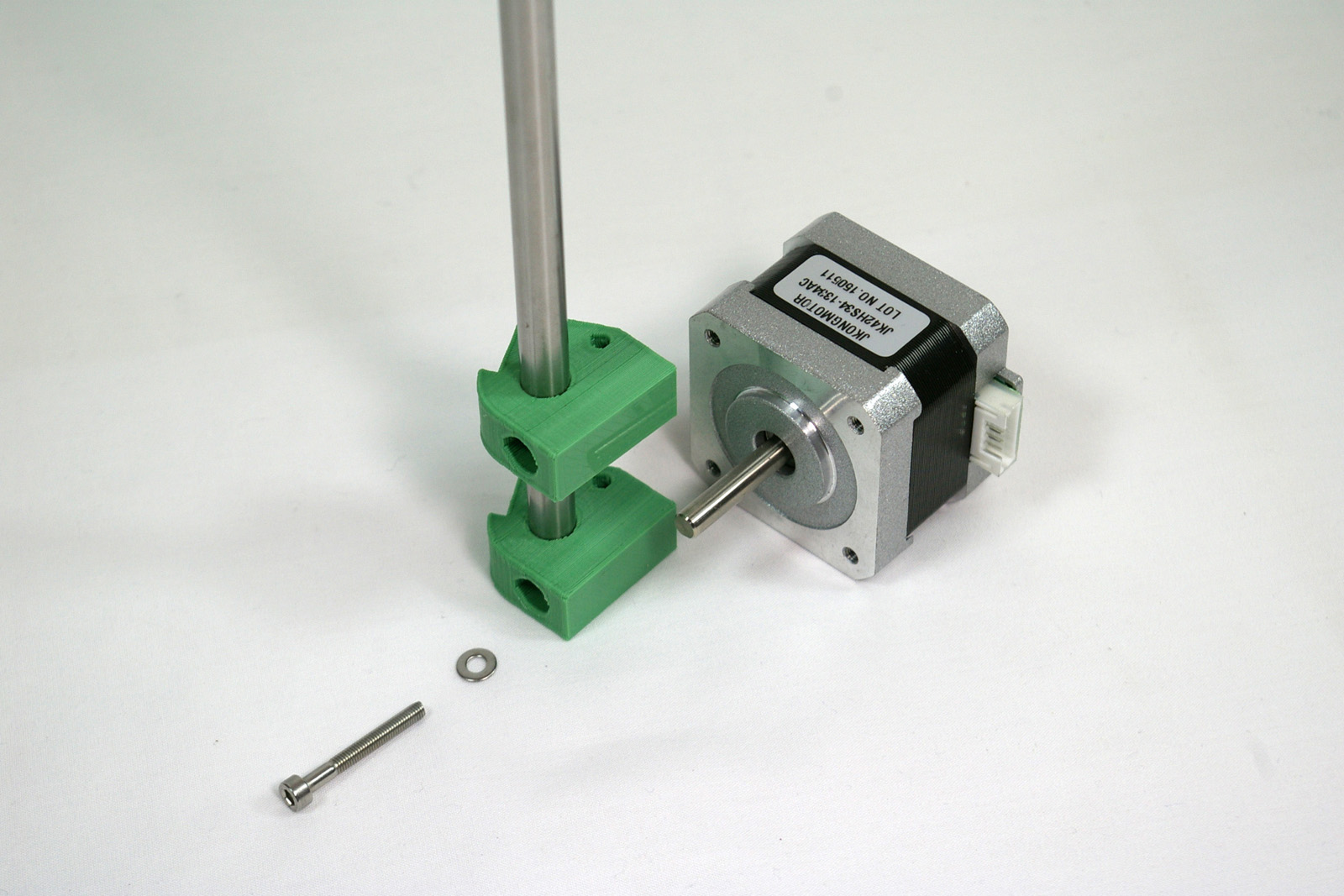
NOTE: The ground bars should have clean chamfered ends, free from burrs, so they can slide easily into the relevant parts without causing any damage. Check all the ground bars before proceeding and file any burrs away as necessary. You may damage the linear bearings when you fit them if you do not do this.
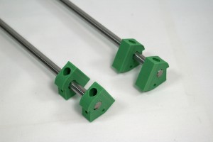
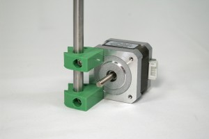
| Push two printed motor brackets onto the end of each smooth rod. Note the orientation, and that the bracket closest to the end of the rod should be flush with the end. |
 |
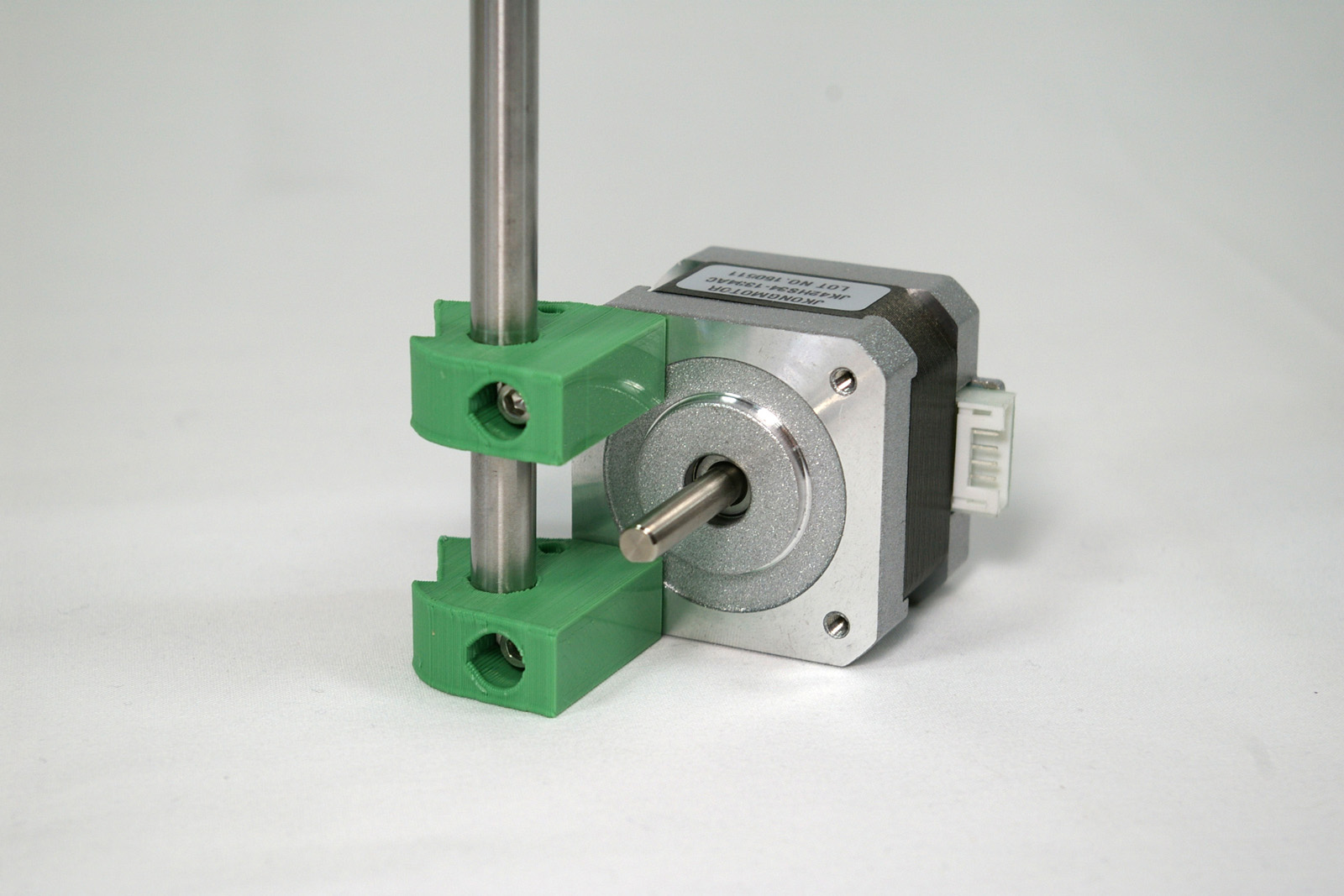
| Screw a M3x25mm cap head screw, through two washers and the motor bracket, and into the motor. Note that the motor wiring connector should come out sideways, not up or down. |
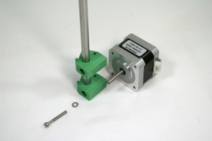 |
| Add a second M3x25mm cap head screw into the top bracket. Slide motor bracket so it lines up with the hole in the motor, and tighten. |
 |
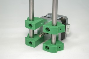
| Repeat for the other side. The screws and washers, when tightened, hold the rods in place so they cannot slip through the motor bracket. Add/remove washers as necessary to ensure the rods can be securely clamped. |
 |
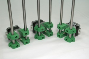
| You need to build three towers in total, so repeat the above twice more. You will need two with motor wiring connectors on one side, and one with it on the other side. See the picture for orientation. |
 |
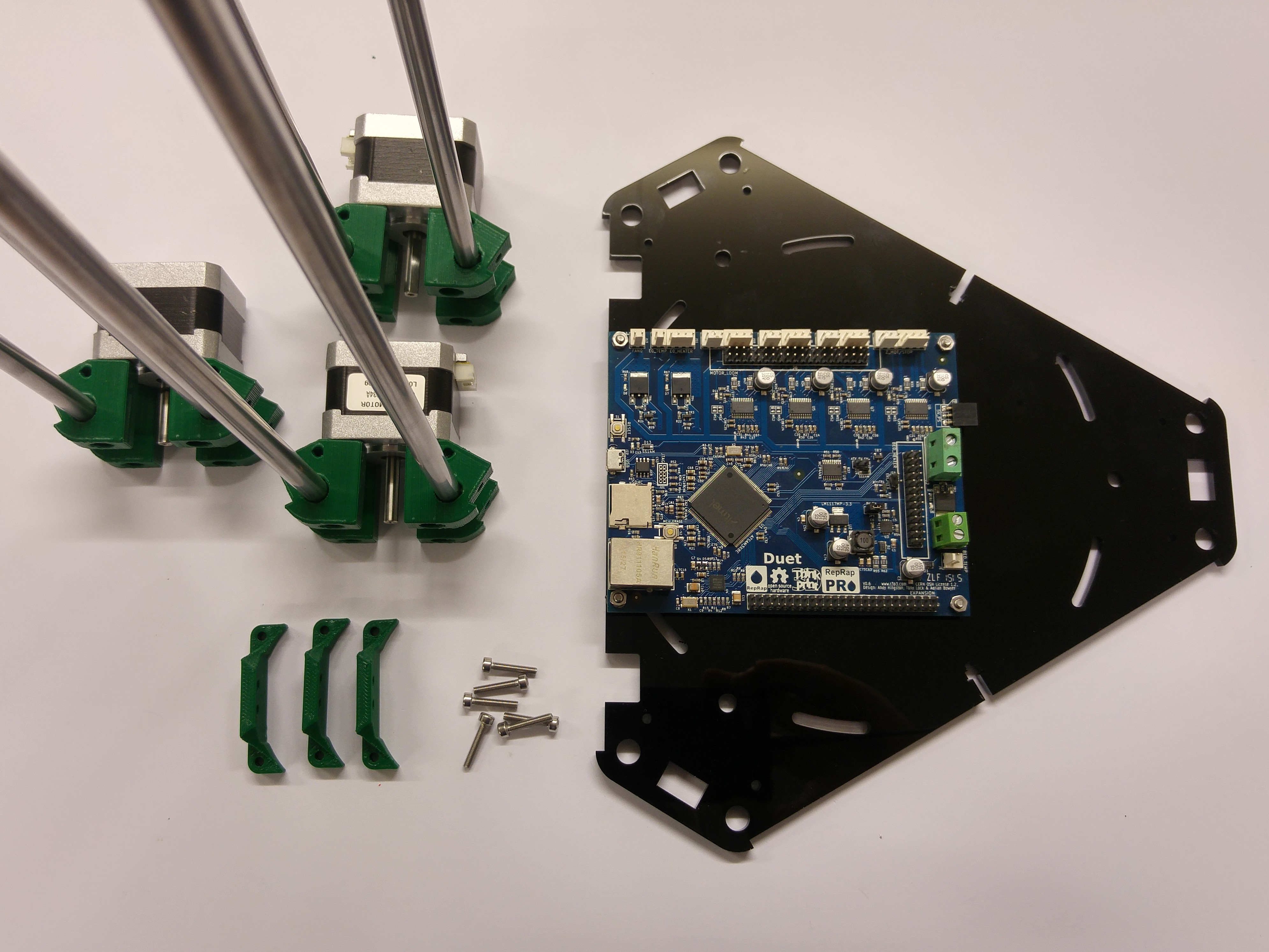
Base plate assembly
The base plate holds the electronics. You will need the following parts:
| # |
Component |
Qty |
Type |
| 1299 |
Base Plate (5mm acrylic) |
1 |
Laser cut |
| 744 |
Duet PCB spacer (5mm acrylic, part of base plate) |
4 |
Laser cut |
| 394 |
Duet PCB |
1 |
Electronics |
| 258 |
M3 Nut |
4 |
Fasteners |
| 1186 |
M3x16mm button head screw |
4 |
Electronics |
| 212 |
M3 plain washer |
4 |
Fastener |
|
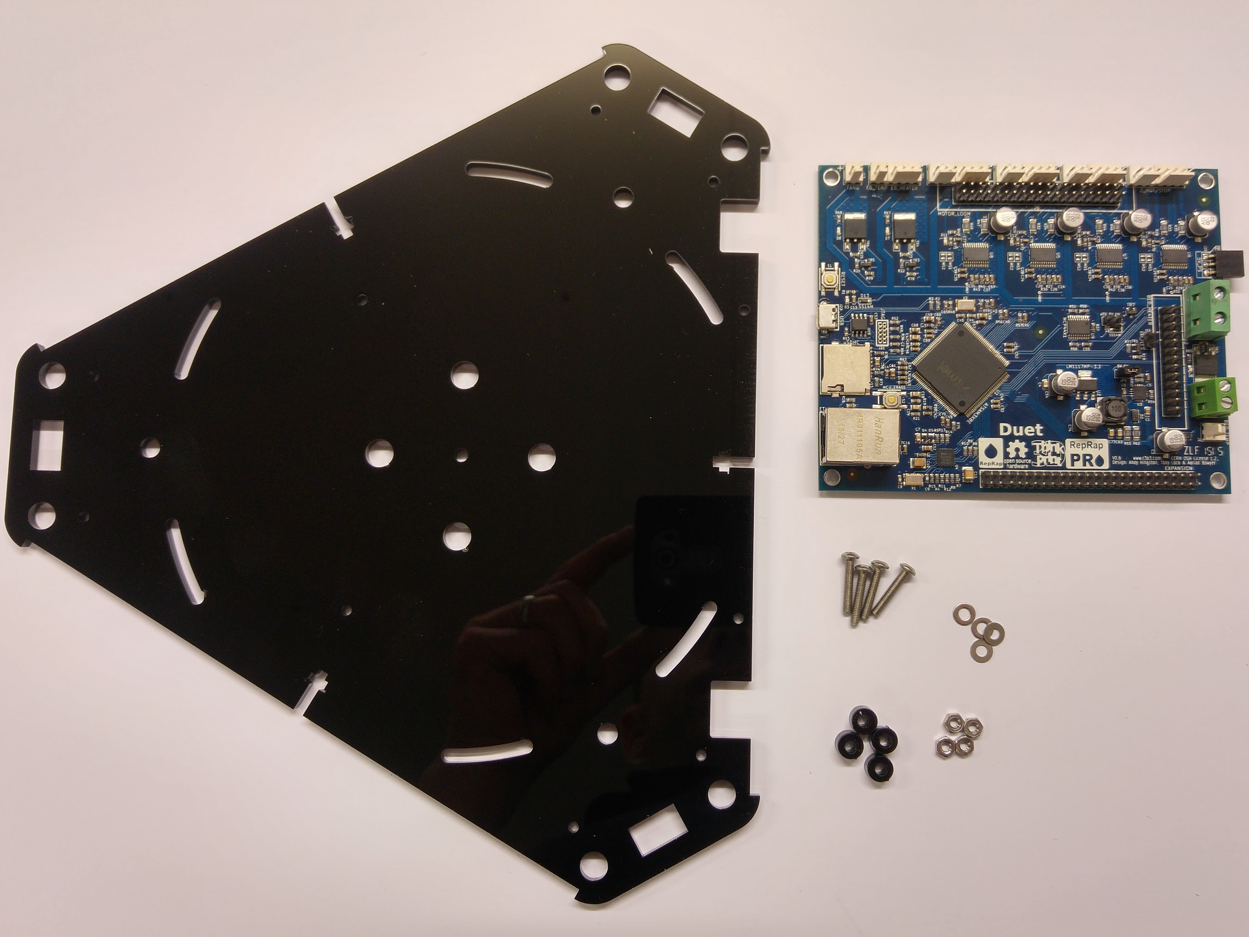 |
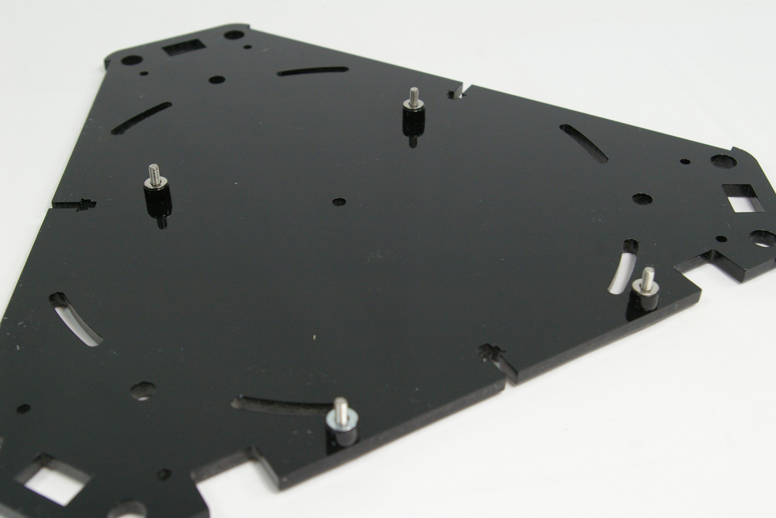
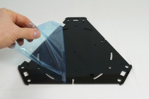
| All acrylic parts are covered by a protective film, on both sides. Always remove this before assembly. The Duet PCB spacers are cut into the base plate, and are attached by a small sprue. Remove them for assembly. |
 |
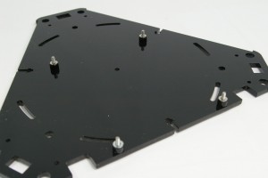
| There are four holes in the base plate, for mounting the Duet PCB. Push an M3x16mm button head screw through each one, and put a Duet PCB spacer and M3 washer on each on. |
 |
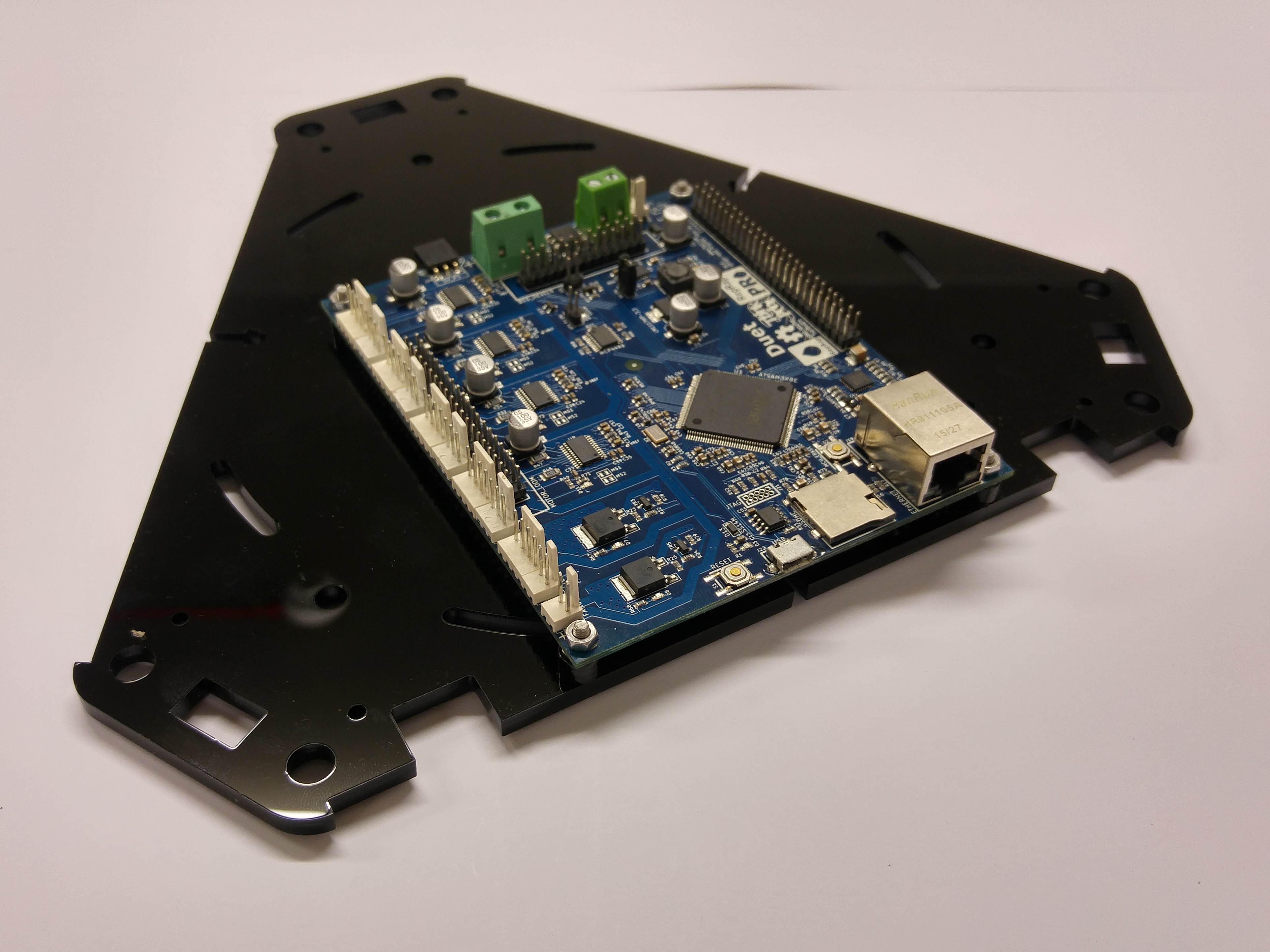
| Place the Duet on these, as shown. Fasten the Duet in place with the four M3 nuts. |
 |
Base assembly
Assemble the lower part of the printer. You will need the following parts:
| # |
Component |
Qty |
Type |
|
Motor towers |
3 |
Assembled |
|
Base |
1 |
Assembled |
| 1245 |
Kinematic Mount |
3 |
Printed |
| 242 |
M3x16mm cap head screw |
6 |
Fastener |
|
 |
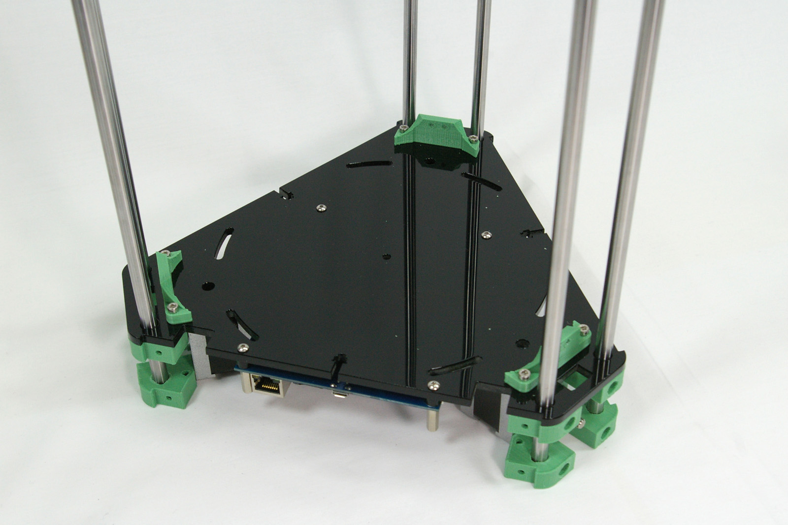
| Push the motors up through the base plate. Be careful to support the rods when doing this; acyrlic can be quite brittle, so you don’t want the ends to move around. Note the orientation of the motor connectors to the Duet; fit them as shown will make wiring them up much easier. |
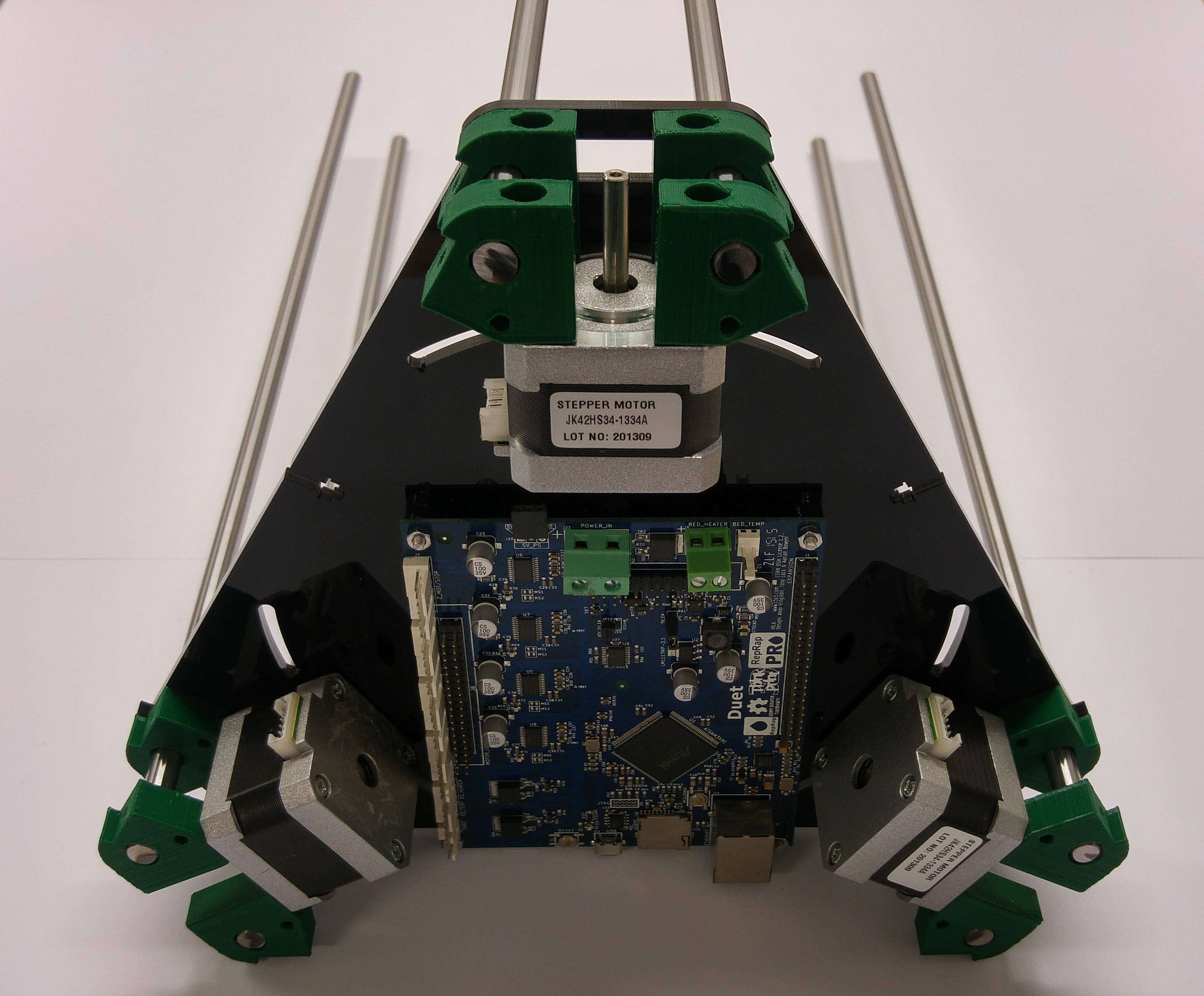 |
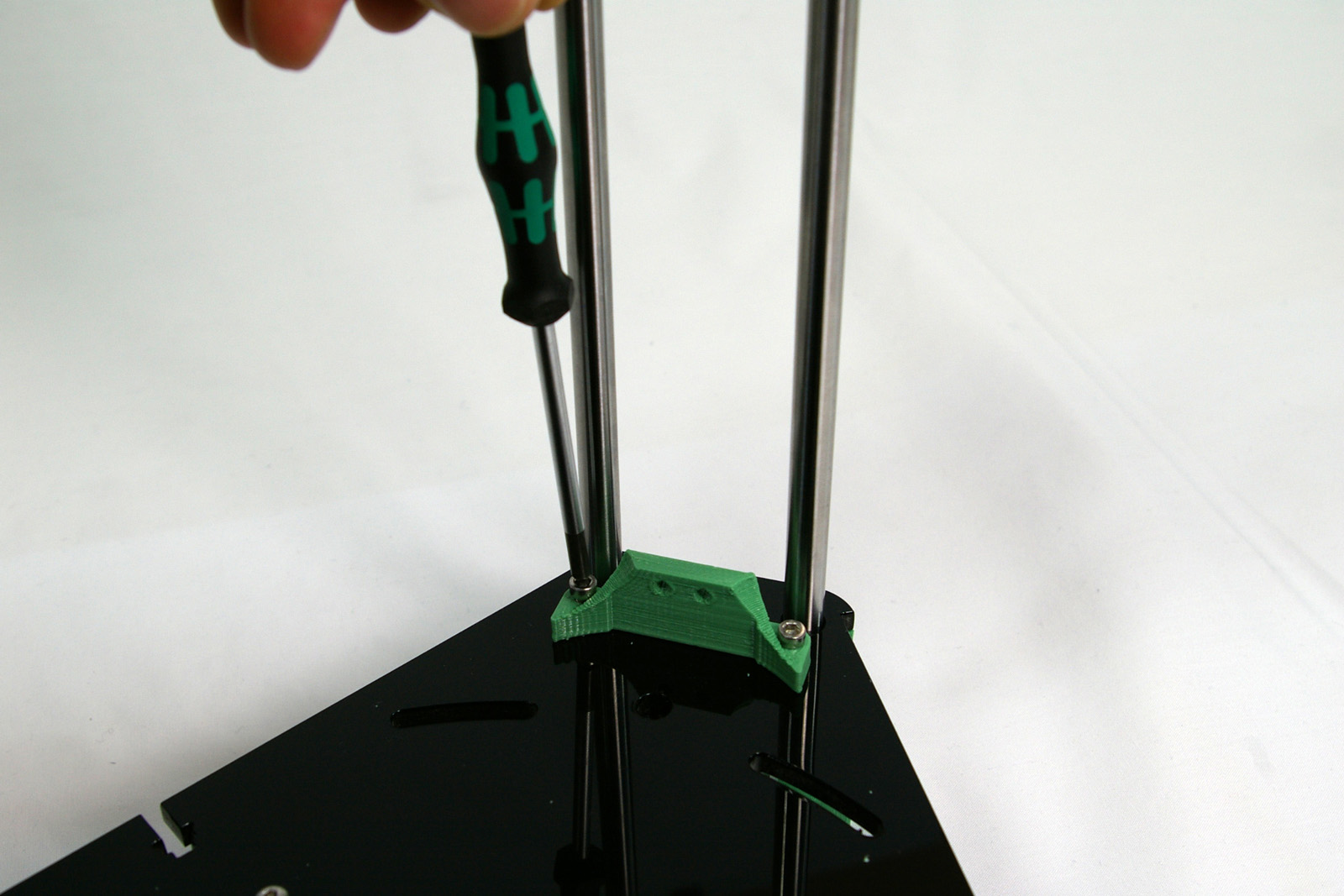
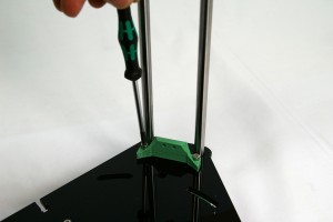
| Using two M3x16mm cap head screws on each, screw the three kinematic mounts onto the base plate. The screws should self-tap into the plastic of the printed motor mount underneath. |
 |
| Your printer should now look like this. |
|