Goal
| By the end of this section, you will have built the hot end, assembled it with the effector, and installed it in the printer frame. |
 |
Assemble the hot end components
The hot end melts the filament, and extrudes it, to build the 3D printed object.
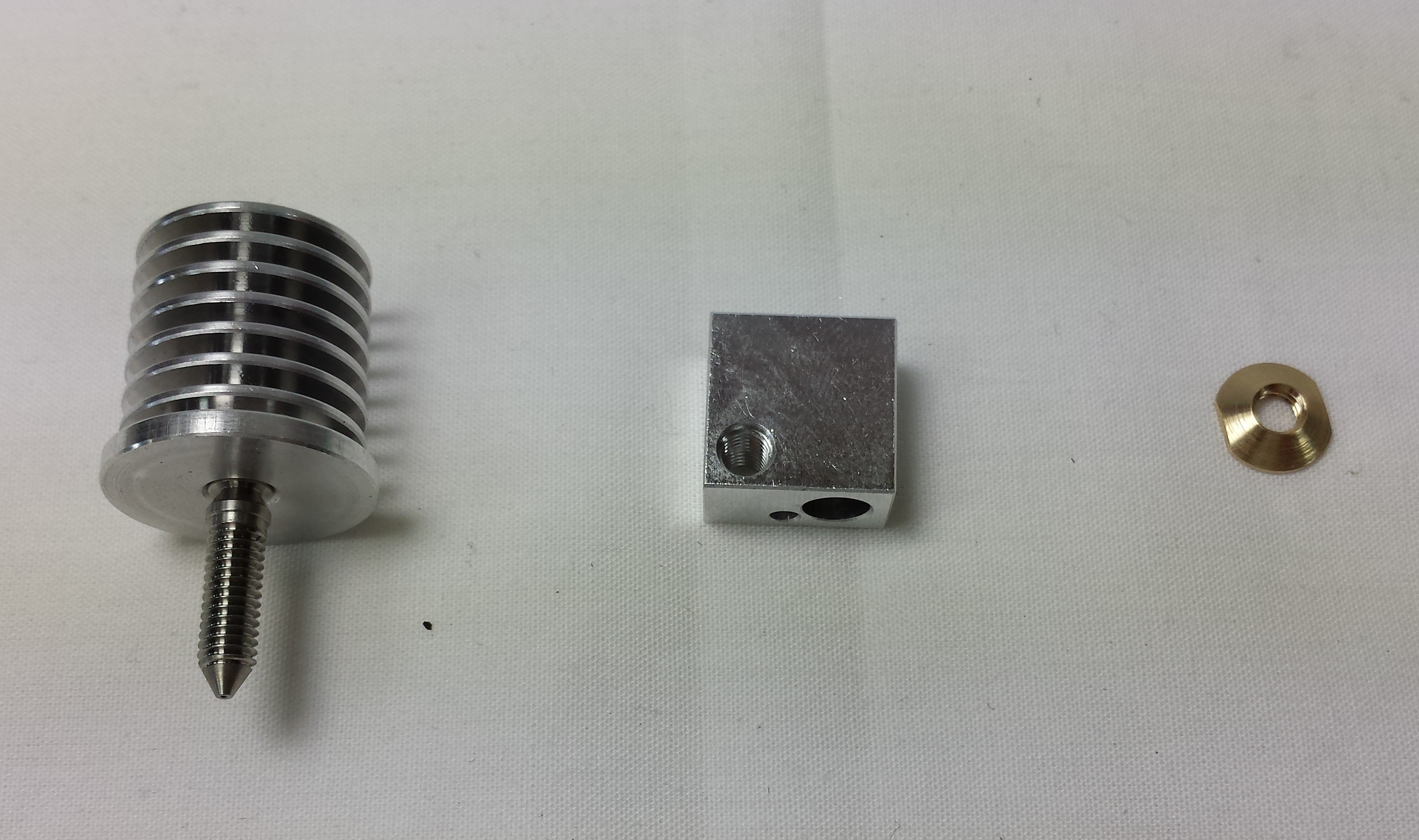
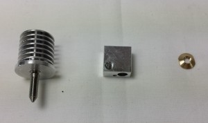
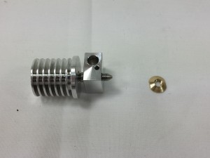
Nozzle assembly
The nozzle is where the filament is heated and extruded from. You will need the following parts:
| # |
Component |
Qty |
Type |
| 1180 |
Brass nut |
1 |
Hot end |
| 739 |
Heater block |
1 |
Hot end |
| 1179 |
Threaded nozzle |
1 |
Hot end |
| 1136 |
Heatsink |
1 |
Hot end |
|
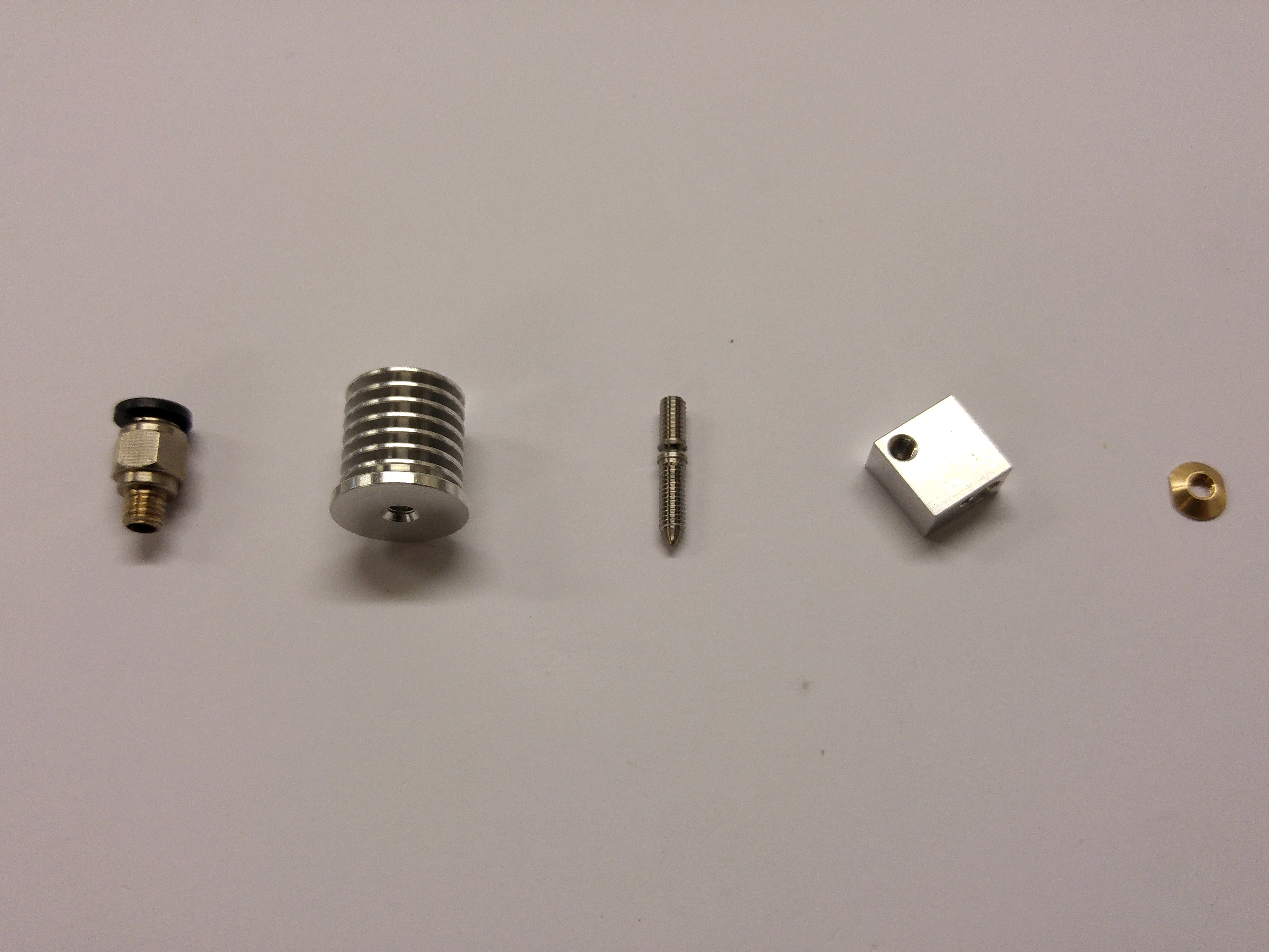 |
| Screw the nozzle into the base of the heatsink by hand. |
 |
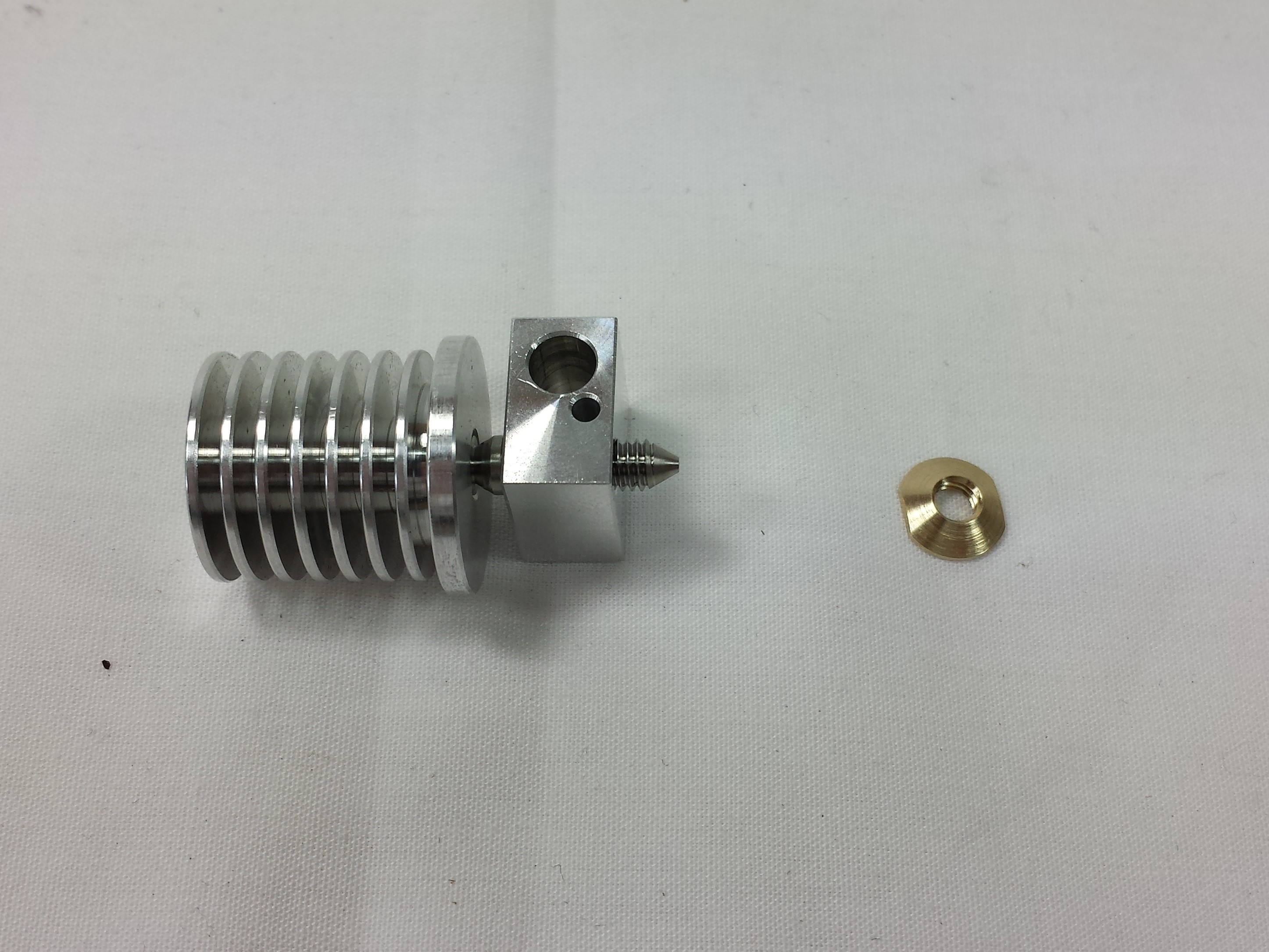
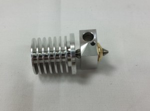
| Screw the heater block onto the nozzle, again by hand. There is not need to use any tools at this stage. Take care to fit the heater block with the small hole nearest the nozzle tip. |
 |
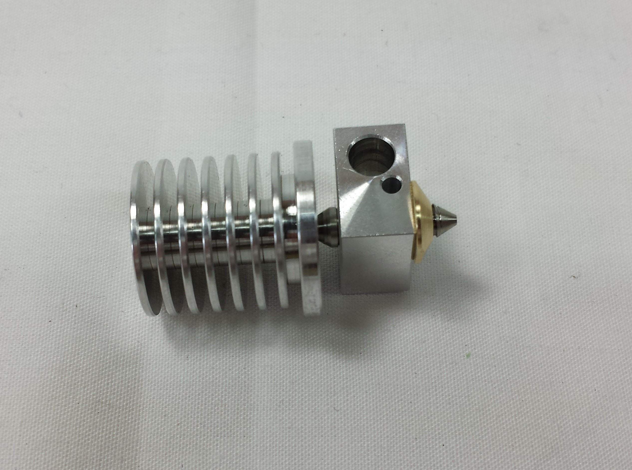
| Fit the brass nut. Using an 8mm spanner, gently tighten the assembly until it is just over ‘finger tight’. The constriction in the nozzle has a very thin wall, so care should be taken not to over tighten the assembly as it may result in snapping the nozzle. |
 |
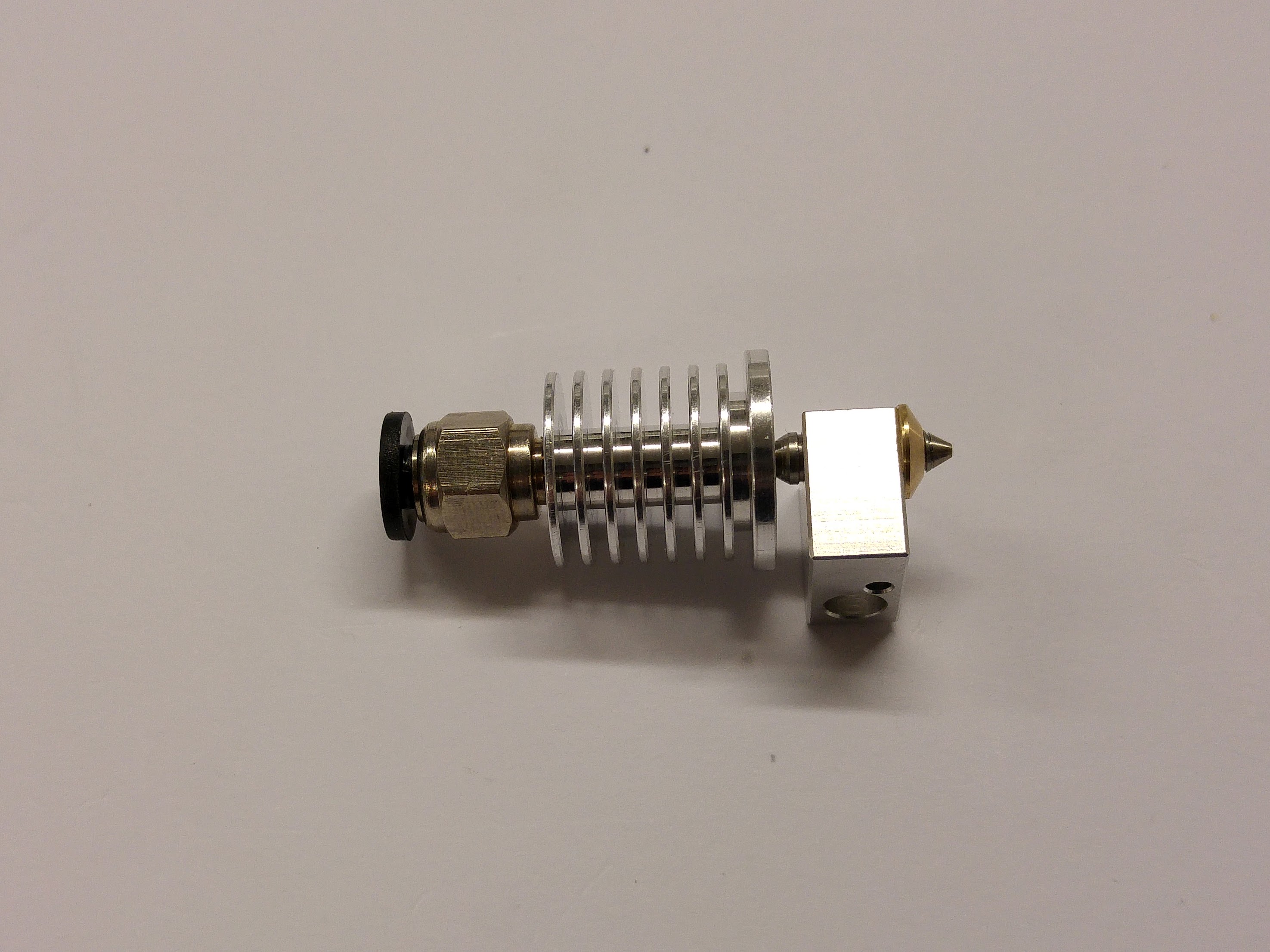
| Screw in the pneumatic fitting to the heatsink. There is no need to use a spanner, hand tightening is sufficient. |
 |
Thermistor
The thermistor is the temperature sensor for the hot end, and makes sure the hot end stays at the correct temperature. So it’s rather vital! You will need the following parts:
| # |
Component |
Qty |
Type |
| 430 |
Thermistor |
1 |
Hot end |
| 167 |
PTFE heatshrink |
1 |
Hot end |
|
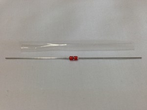 |
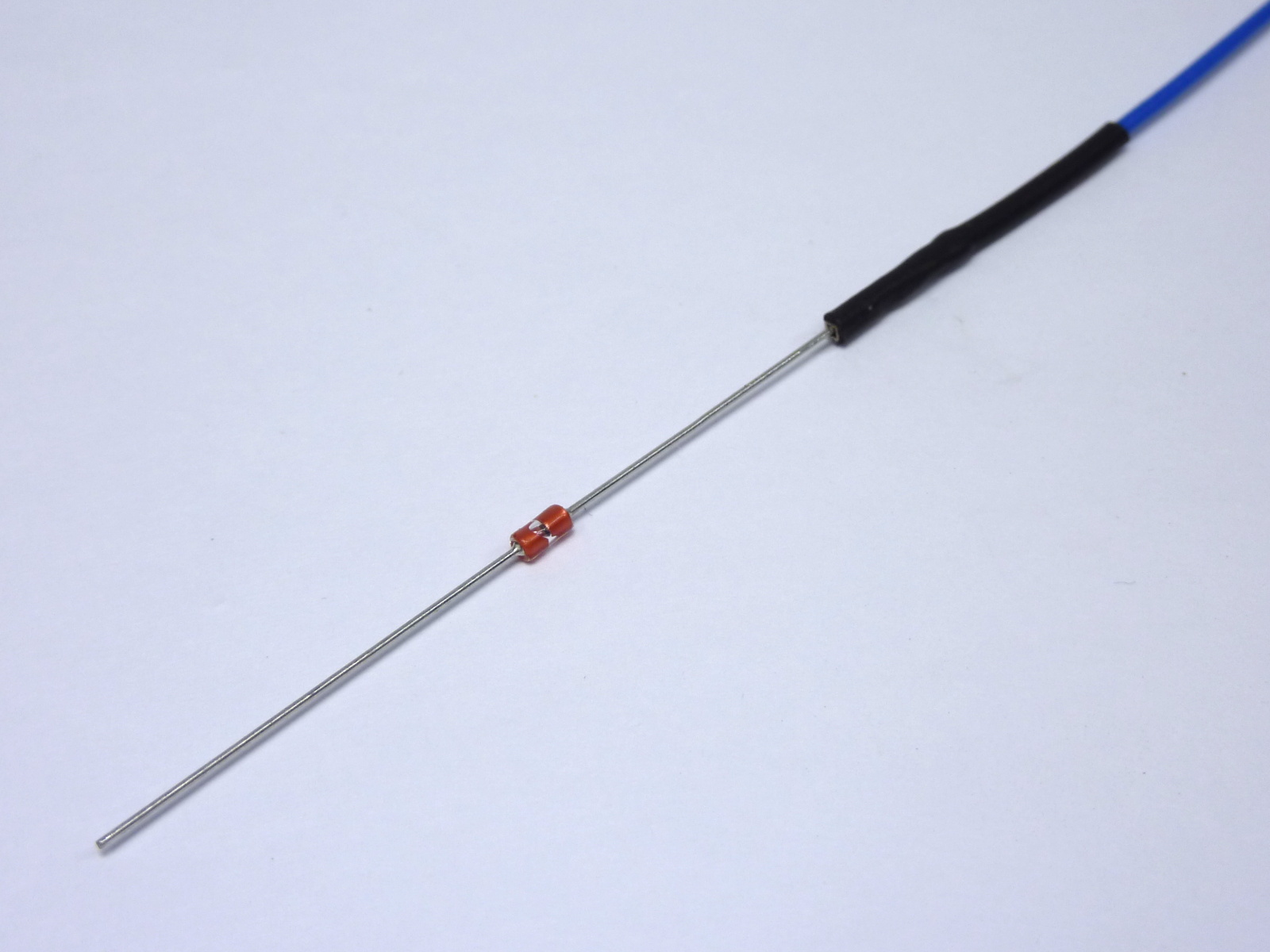
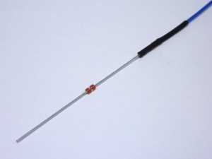
| This is how the thermistor should look with the PTFE shrunk onto it. |
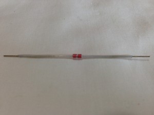 |
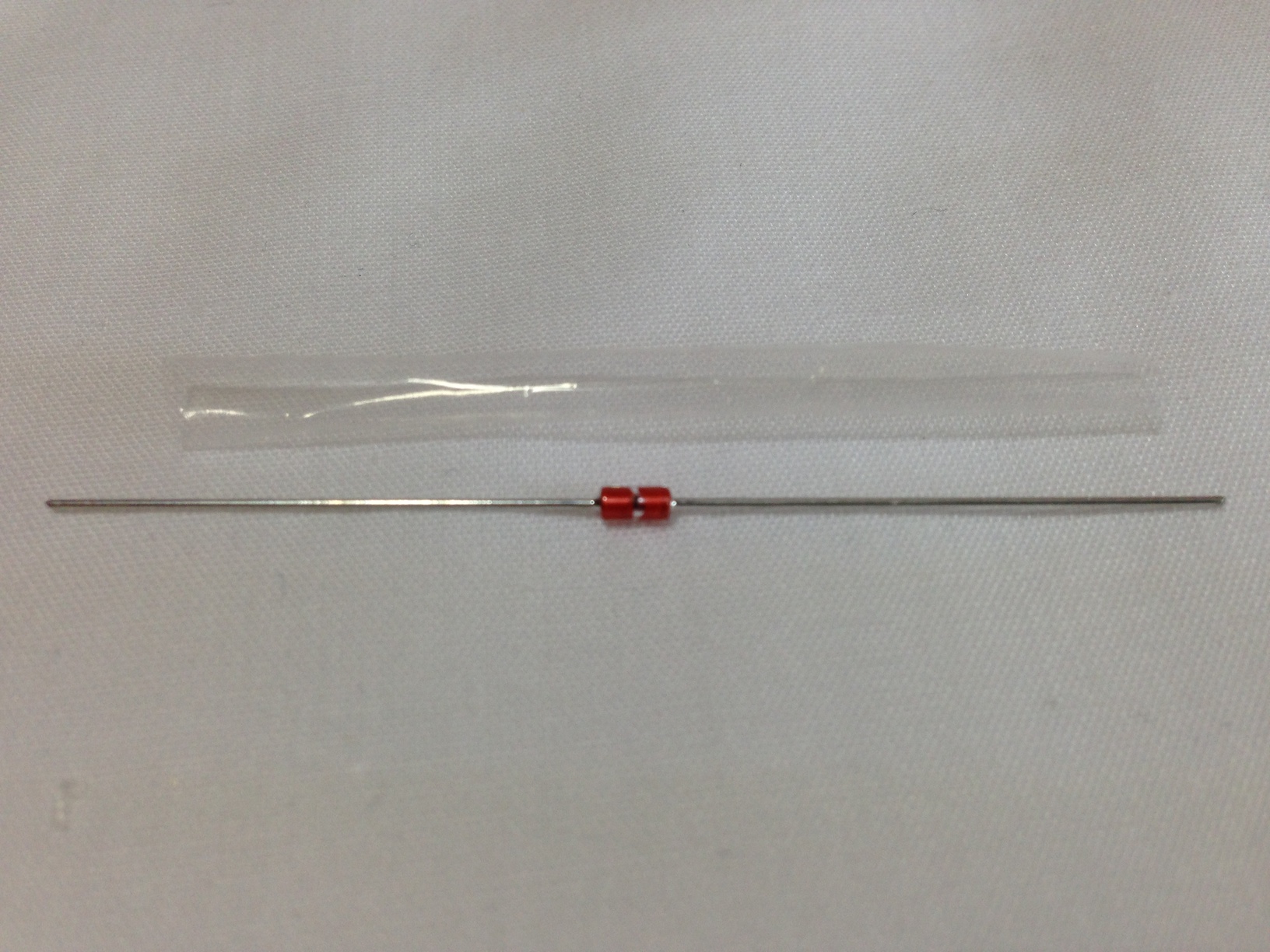
| Cut the transparent PTFE heatshrink about 8mm shorter than the thermistor with its axial connecting wires. Put the thermistor in it so that 4mm of wire protrudes from each end. |
|
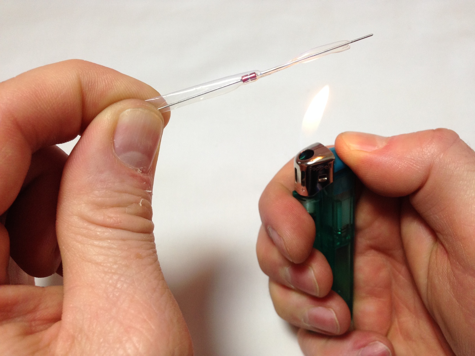
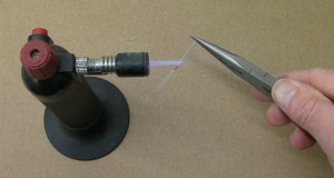
| Using a flame (a cigarette lighter, blowtorch, gas hob, or hot air gun work well; a hair dryer does not), shrink the heatshrink over the thermistor. Just waft the thermistor and heatshrink through the flame. You don’t want the heatshrink to overheat and to burn. |
 |
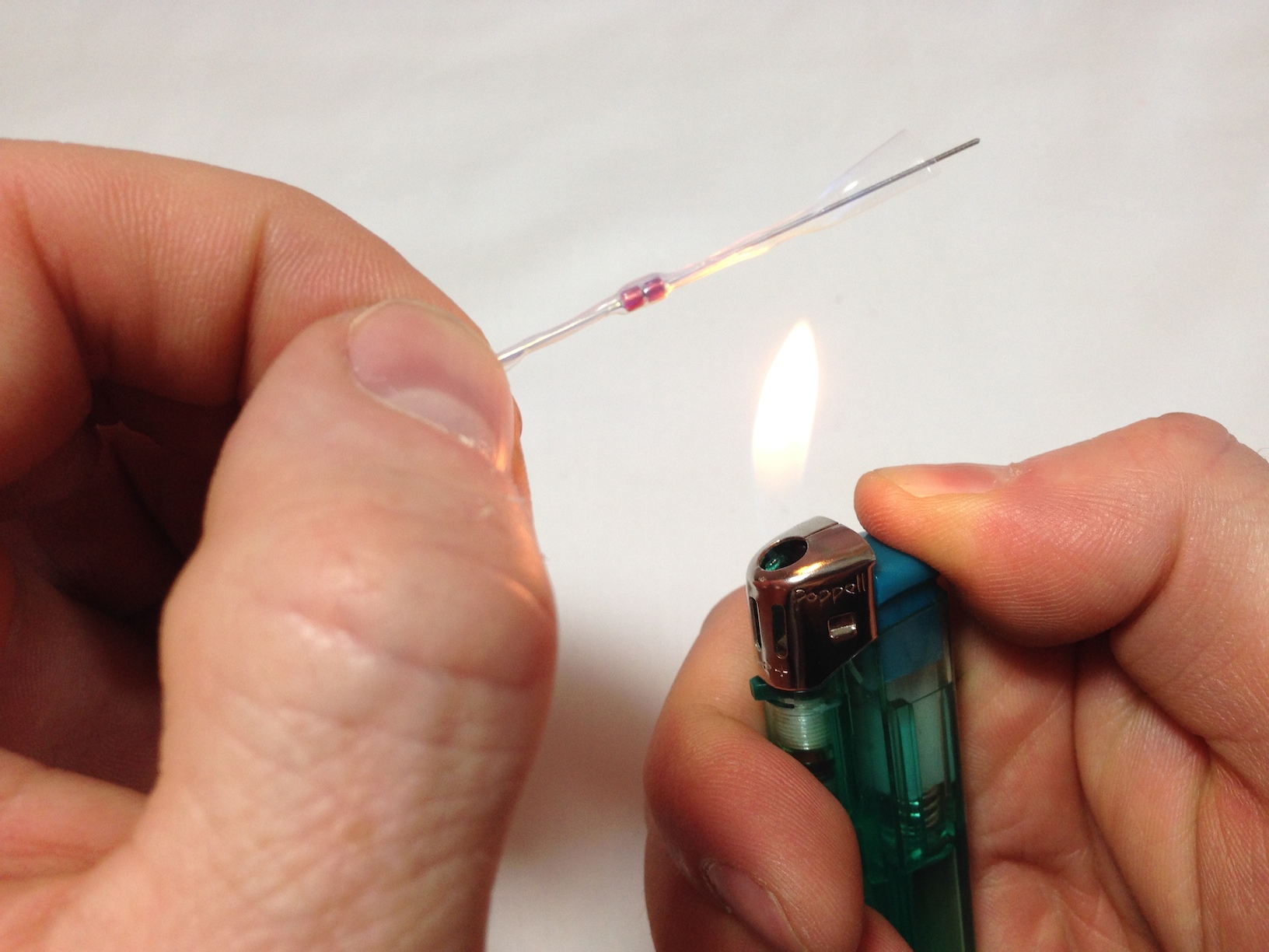
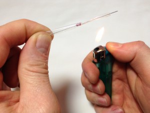
| If you’re doing this with a cigarette lighter, hold the thermistor at one end, and heat the heatshrink from the middle out to the other end. The heatshrink will be transparent when it has fully shrunk, and will then go back to opaque when the heat is removed. Keep it above, not in, the flame, so it doesn’t overheat and go black. |
 |
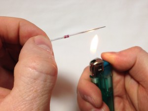
| Let it cool for a few moments, then turn it around and do the other side. Rolling the thermistor between your fingers while heating will improve the consistency of the heatshink. |
 |
| Turn it around again and heat the first side, rolling it in your fingers, to get a really good, even heatshrink. Make sure it has shrunk properly around the central bulge, or it won’t fit easily into the heater block. |
 |
| This is how the thermistor should look with the PTFE shrunk onto it. |
|
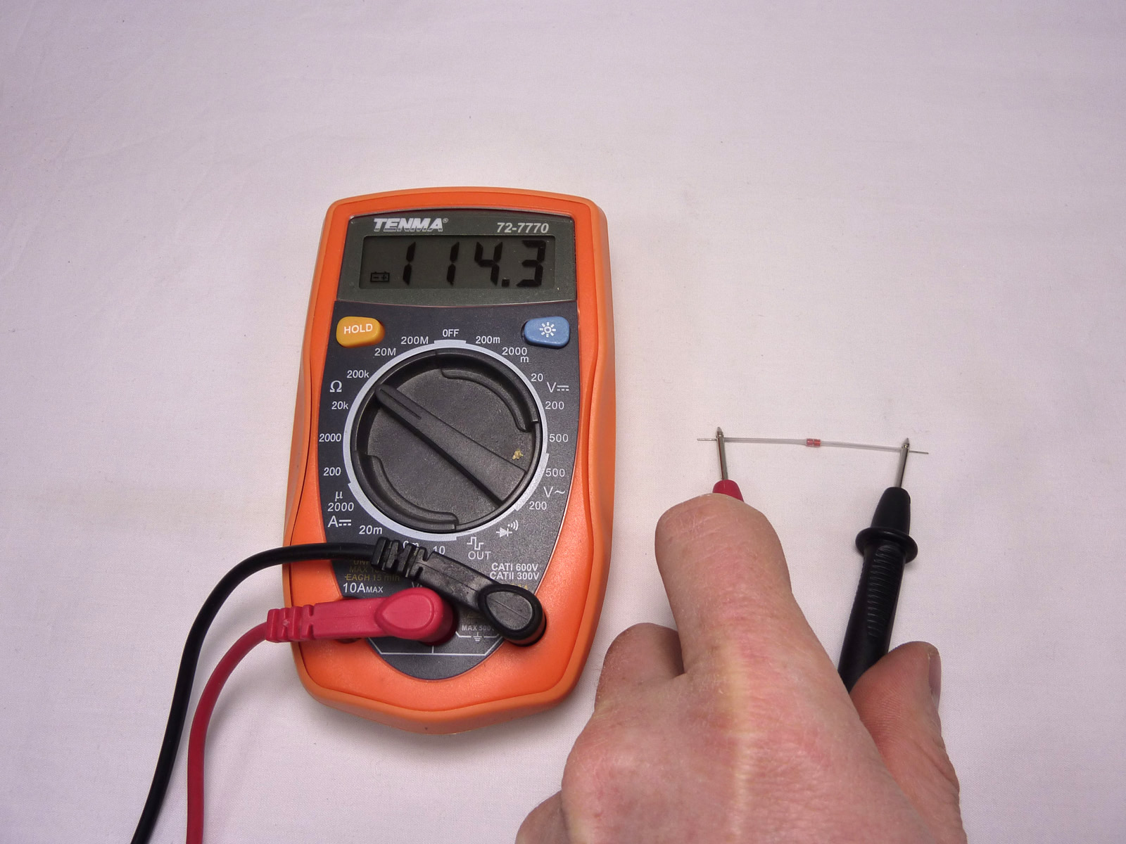
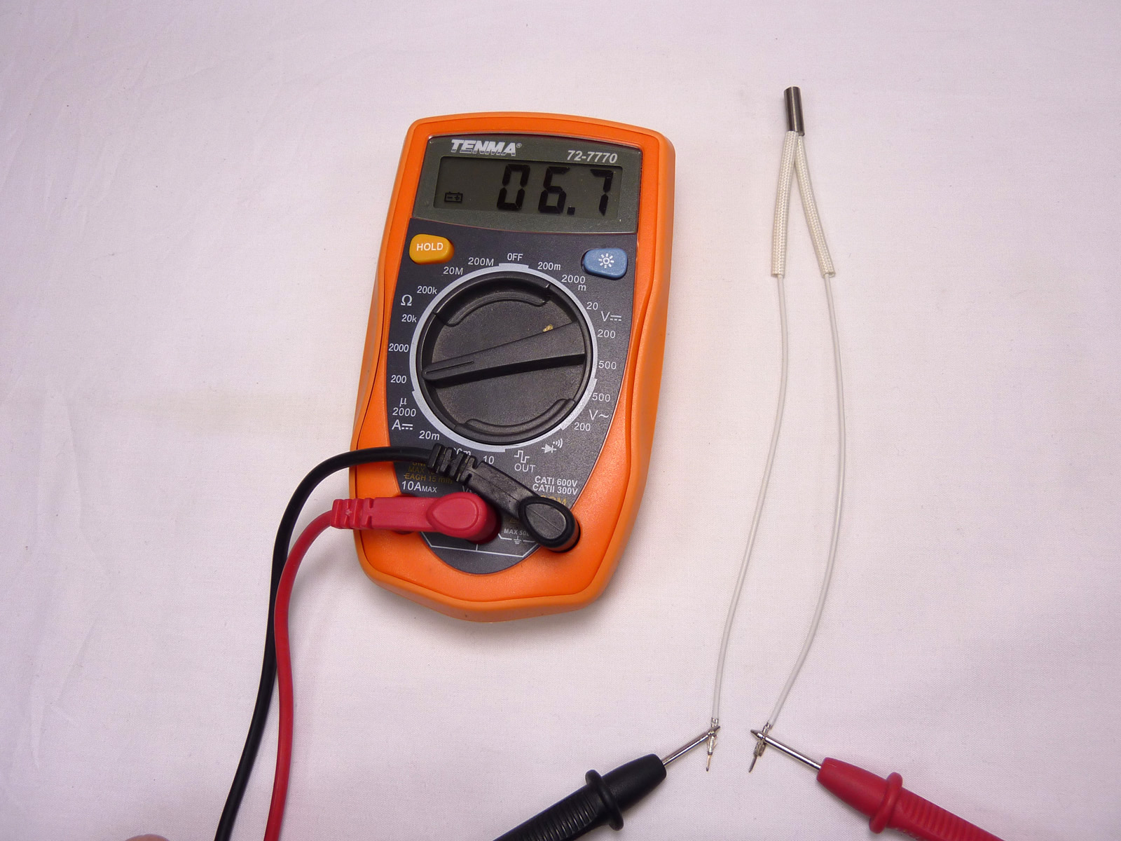
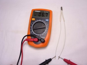
| Test the resistance of the thermistor with a multimeter. It should be around 100k ohms at an ambient temperature of 25C. Like the heated bed thermistor, the resistance will be greater if it is colder, and less if hotter. |
 |
Test the cartridge heater
The cartridge heater provides the heat for the hot end. You will need the following parts:
| # |
Component |
Qty |
Type |
| 314 |
Cartridge heater 19v |
1 |
Hot end |
|
Picture to come |
| Check the resistance of the heater cartridge. It should be around 7.0 ohms. |
 |
Thermistor wires
These wires connect the thermistor to the wiring loom.
| # |
Component |
Qty |
Type |
| 433 |
Thermistor wiring – 160mm |
2 |
Hot end |
| 197 |
2.4mm Black heatshrink |
as needed |
Hot end |
|
New picture to come |
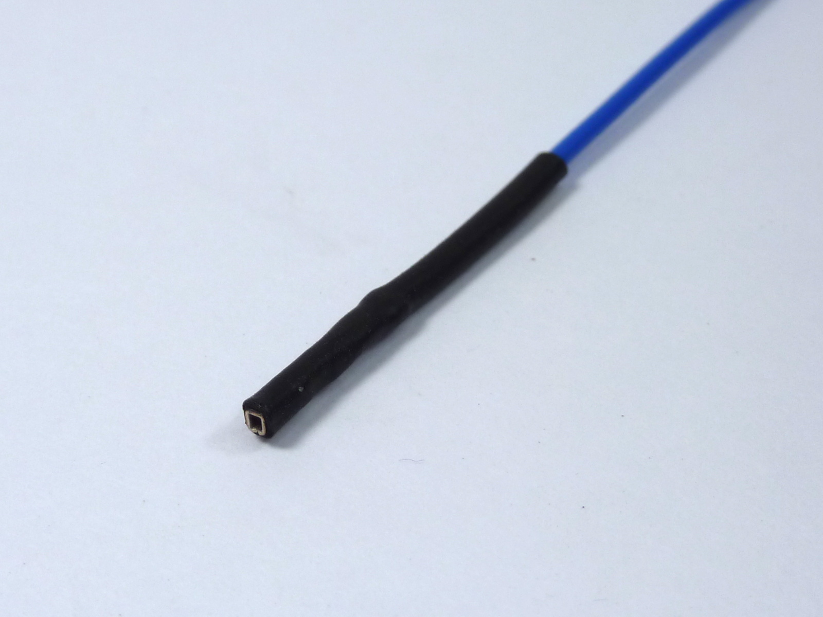
| Thermistor wires should each have the female terminal wrapped in heatshrink. |
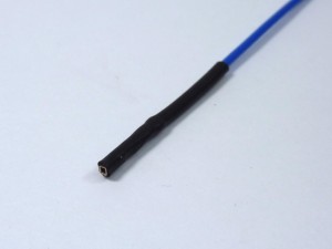 |
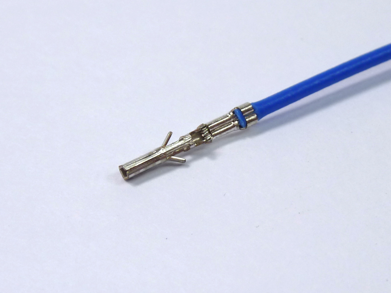
| If your thermistor wiring is supplied without heatshrink on both ends, and the female end looks like this, do the following. |
 |
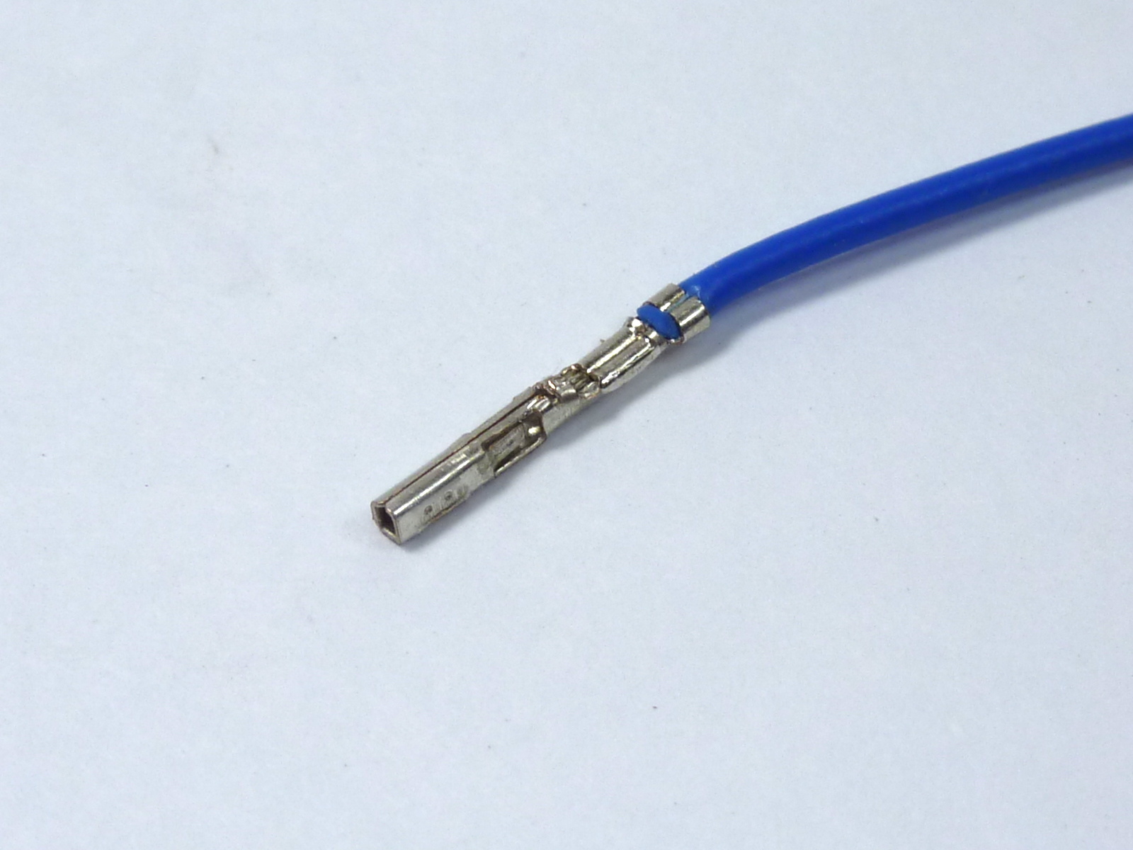
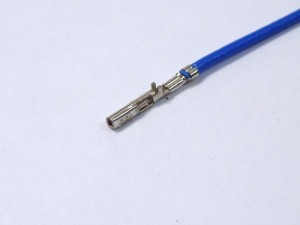
| Fold in the two barbs that stick out the side, as shown in the first picture; a small screwdriver or tool with a point is easiest. They need to fold into the crimp, as they will hold the thermistor wire. |
 |
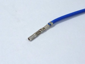
| Also flatten the top two tabs, so the crimp is smooth. If you put the heatshrink on with them sticking up, they can cut through the heatshrink, and cause a short circuit if they touch other metal. |
 |
| Put the heatshrink on the end of the wire, covering the crimp but leaving the end open. |
|
| Check that it holds the thermistor firmly. You will cover the thermistor with high temperature PTFE heatshrink in the next step; you want as little metal showing as possible between the PTFE heatshrink and the black heatshrink, to avoid short circuits to metal parts of the printer. |
 |
Assemble the hot end and effector
The hot end is mounted in the effector. You will need the following parts:
| # |
Component |
Qty |
Type |
|
Hot end assembly |
1 |
Assembled |
|
Effector assembly |
1 |
Assembled |
| 113 |
M3x25mm hex head screw |
1 |
Fastener |
| 242 |
M3x12mm cap head screw |
2 |
Fastener |
| 212 |
M3 plain washer |
2 |
Fastener |
| 368 |
3×2 Female Housing (3020-06) |
1 |
Hot end |
| 314 |
Cartridge heater 19v |
1 |
Hot end |
| 433 |
Thermistor wiring -160mm |
2 |
Hot end |
|
Thermistor (insulated) |
1 |
Assembled |
| 1194 |
50mm blower fan – 160mm crimped |
1 |
Electronics |
| 133 |
Cable ties 2mm |
2 |
Electronics |
|
 |
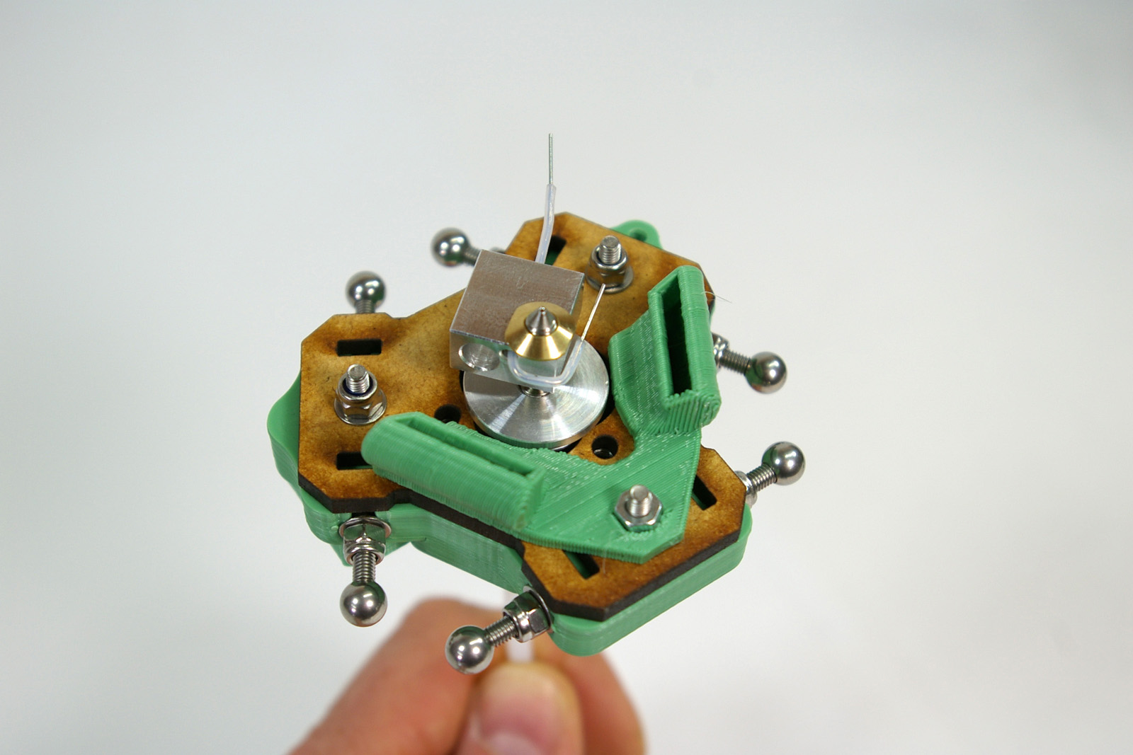
| Pull the thermistor through the heater block. If you use pliers, use them on the PTFE heatshrink, NOT on the metal legs of the thermistor; you are likely to break the thermistor. Ensure the thermistor bead is seated centrally inside the heater block. |
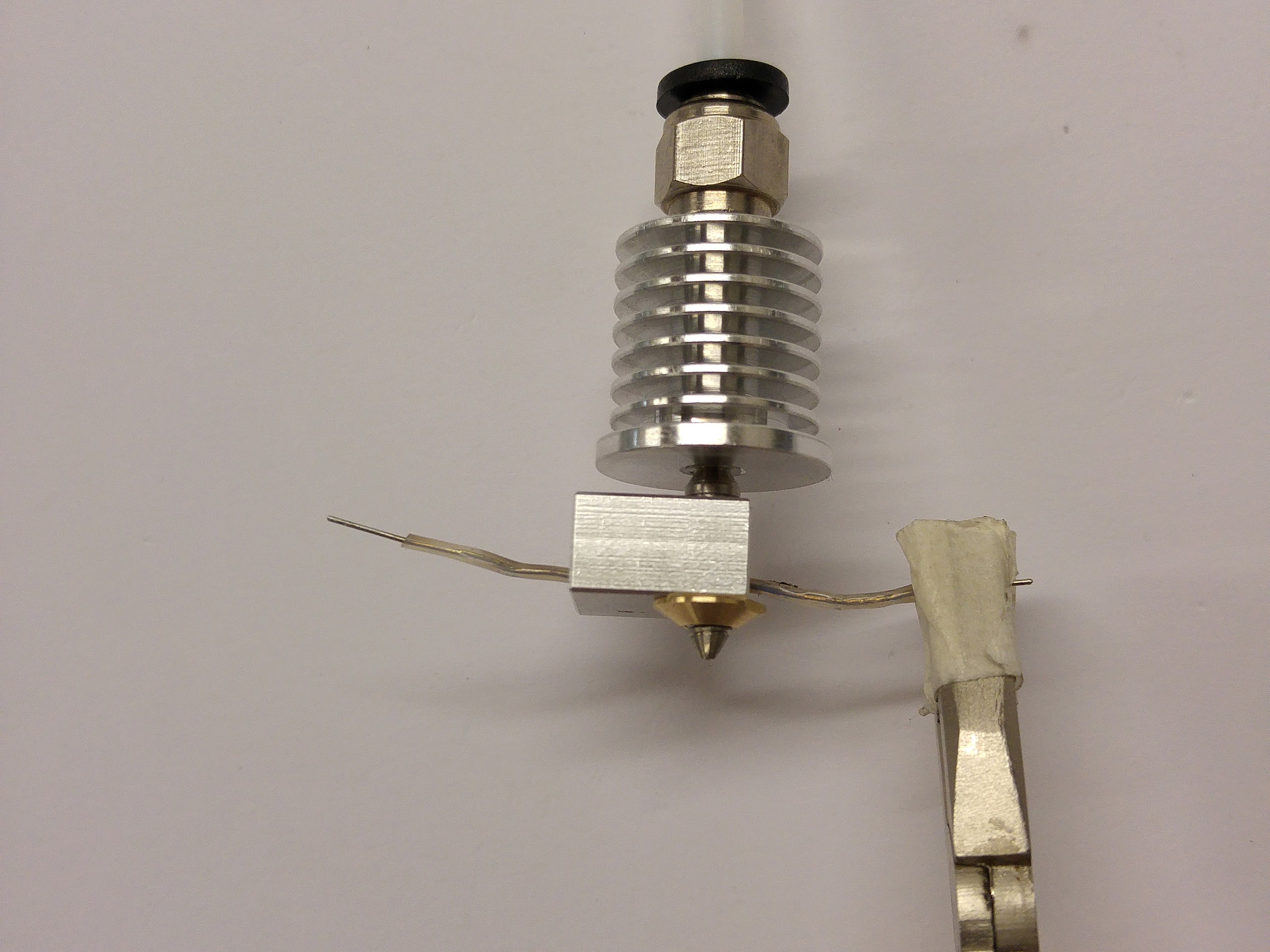 |
| Push the hot end into the effector, orientated as shown. This may require a small amount of trimming of the printed effector part, but it is supposed to be a close fit. Do not trim the MDF effector plate; the hot end has a flange that sits on this. Bend the thermistor leg around the heater block; this ensures it can’t fall out. If the nozzle comes loose in the heatsink, taken the hot end out, tighten, and put it back in again. |
 |
| This picture shows the lower flange of the heatsink sitting on the MDF effector plate. |
 |
| Secure the hot end in place using the two M3x12mm cap head screws and M3 washers as shown. Take care to orient the heater block as shown, without loosening the nozzle in the heatsink, before tightening the M3 nuts. |
 |
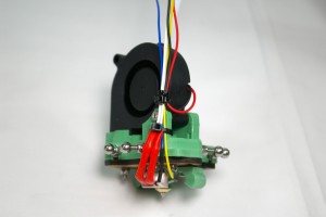
Adding the heater, thermistor and fan
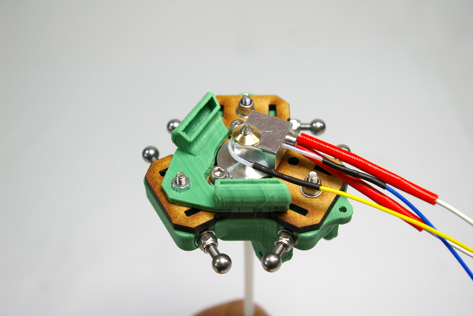
| Connect the thermistor wires to the thermistor, and push the heater cartridge into the larger hole in the heater block. All wires should come out the same way. |
 |
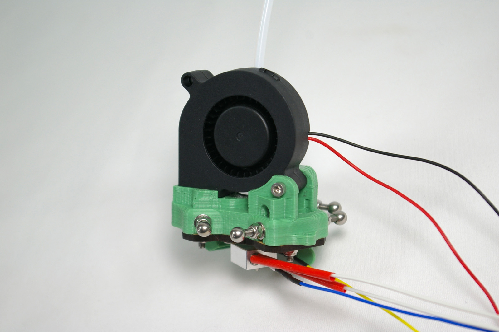
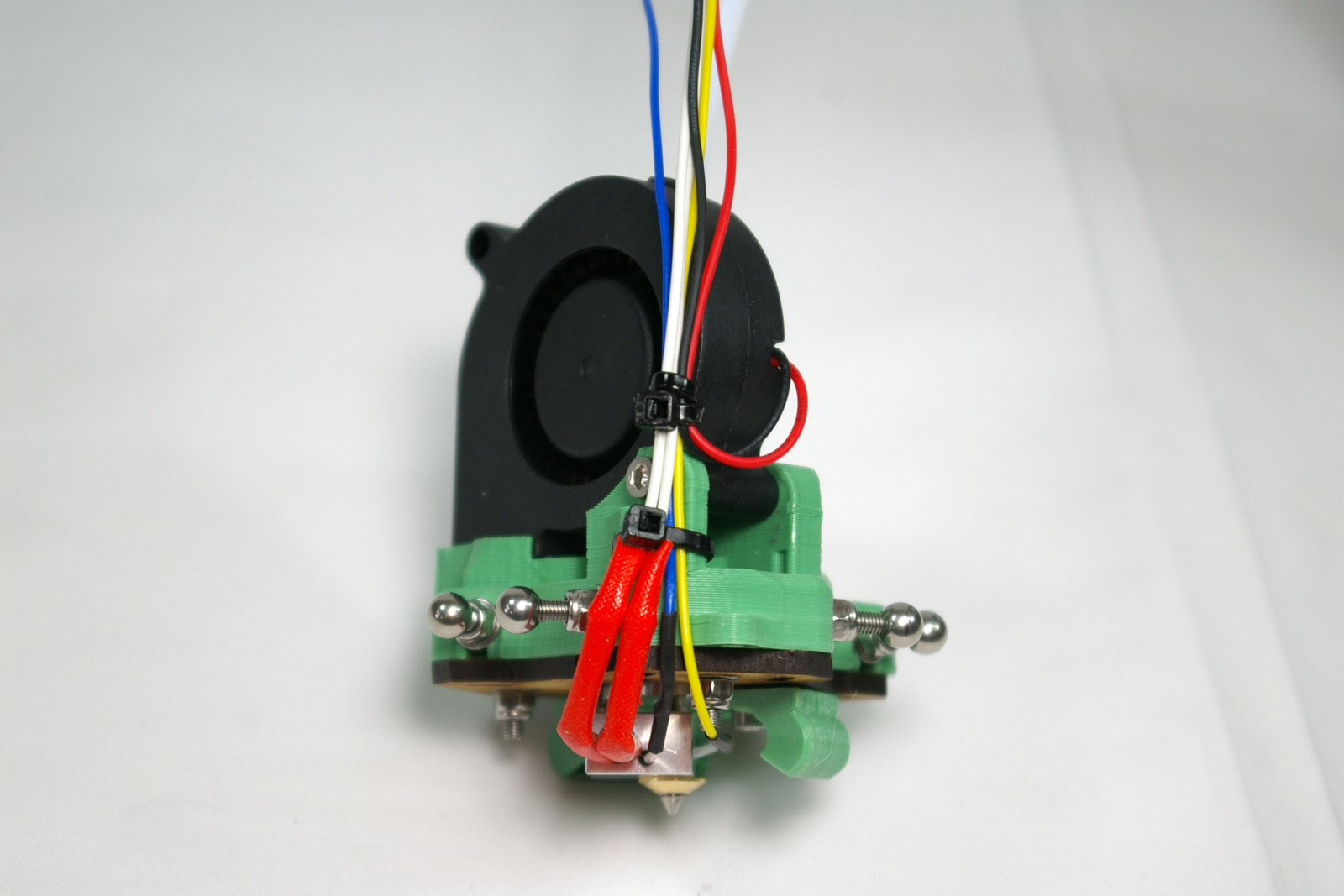
| Fit the fan into the printed effector. It should be a snug fit. Using the M3x25mm hex head screw, fasten it in place. This self taps into the printed part. |
 |
| Secure the fan and hot end wires with the cable ties. Make sure the thermistor and heater cartridge are still fully inserted in the heater block. Try to cable tie the wires to keep them as close in to the effector as possible. |
 |
Hot end wiring
CAUTION! The next step describes wiring up the hot end connector. GREAT CARE should be taken doing this. The heater cartridge and the fan wires have 19V running through them ALL THE TIME. The thermistor wires are 3.3V, and connect directly to the Arduino chip on the Duet. If you incorrectly wire the plug, a short circuit between the thermistor wires and any of the other wires MAY DESTROY YOUR DUET!
Wiring diagram
NOTE: The wiring diagram below, and pictures, show RED heater cartridge wires. Yours will be WHITE.
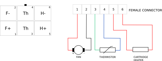
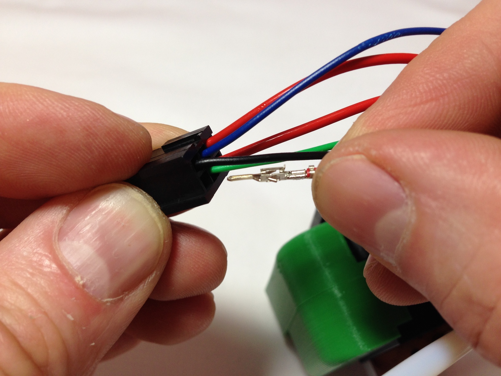
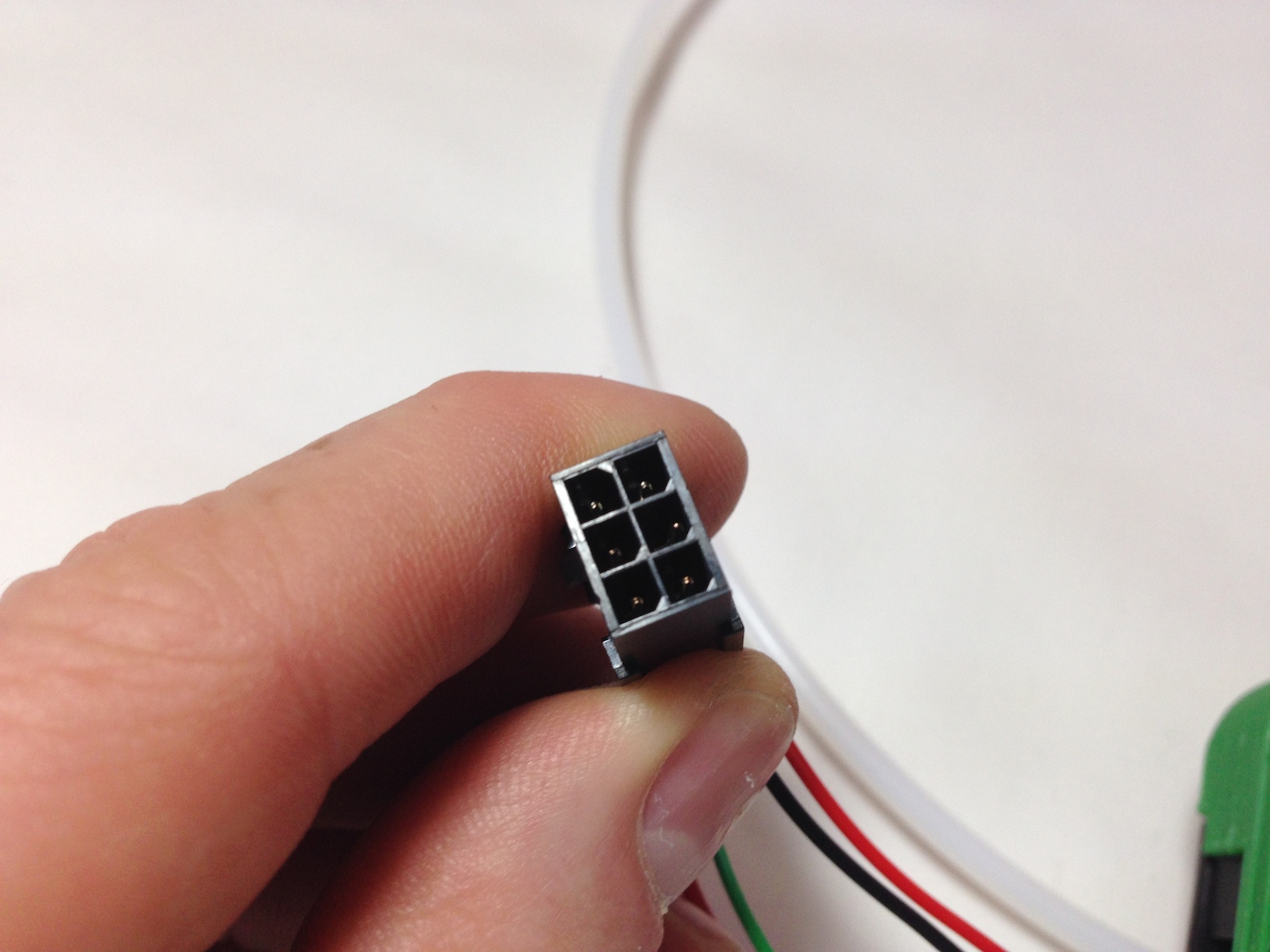
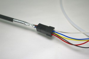
| Put the pins on the ends of the wires into the six-way female socket. The wiring diagram, above, is looking into the back of the socket, where you insert the crimps. The little black rectangle is the locking tab, and the housing has small embossed ‘1’ and ‘6’ numbers on it, so you can orientate it as the diagram. The pins are crimped on one side, and smooth on the other. The smooth sides go downwards in the diagram. |
 |
| Neither the thermistor nor the heater cartridge have a polarity so it doesn’t matter which way round their wires go. (Though the H+ and H- are the way that the machine will apply power – hence the labels.) Make sure to get the polarity of the fan right. This picture shows one of the fan wires being put into the housing, but it is not fully in yet; you can’t see the crimp easily when it is. |
 |
| Check that the pins are all the same depth into the housing. The pins are very difficult to remove without damaging them, so check twice, plug in once! They should click into place, and then shouldn’t easily push further through, or pull back out. |
 |
Wire colours, related to hot end wiring loom
| Wiring loom |
Hot end wires |
| 1 Yellow |
Red FAN wire (+19V) |
| 2 White |
Black FAN wire (ground) |
| 3 Green |
Thermistor wire (green/blue/yellow, 3.3V) |
| 4 Blue |
Thermistor wire (green/blue/yellow, 3.3V) |
| 5 Purple |
Thick WHITE heater wire (+19V) |
| 5 Black |
| 6 Red |
Thick WHITE heater wire (ground) |
| 6 Brown |
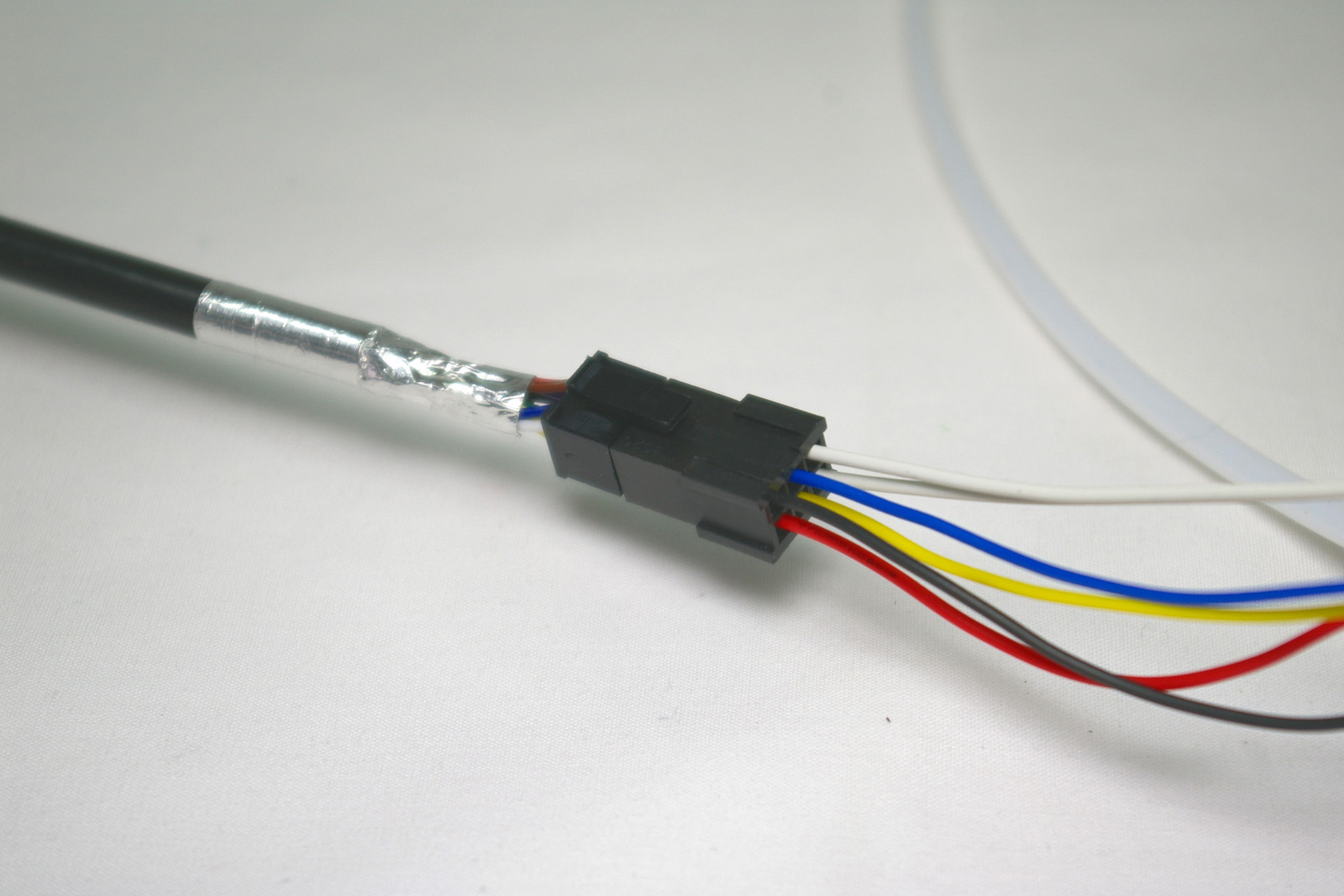
| You can check the wire order by comparing it to the end of the hot end loom, which the hot end plugs into. |
 |
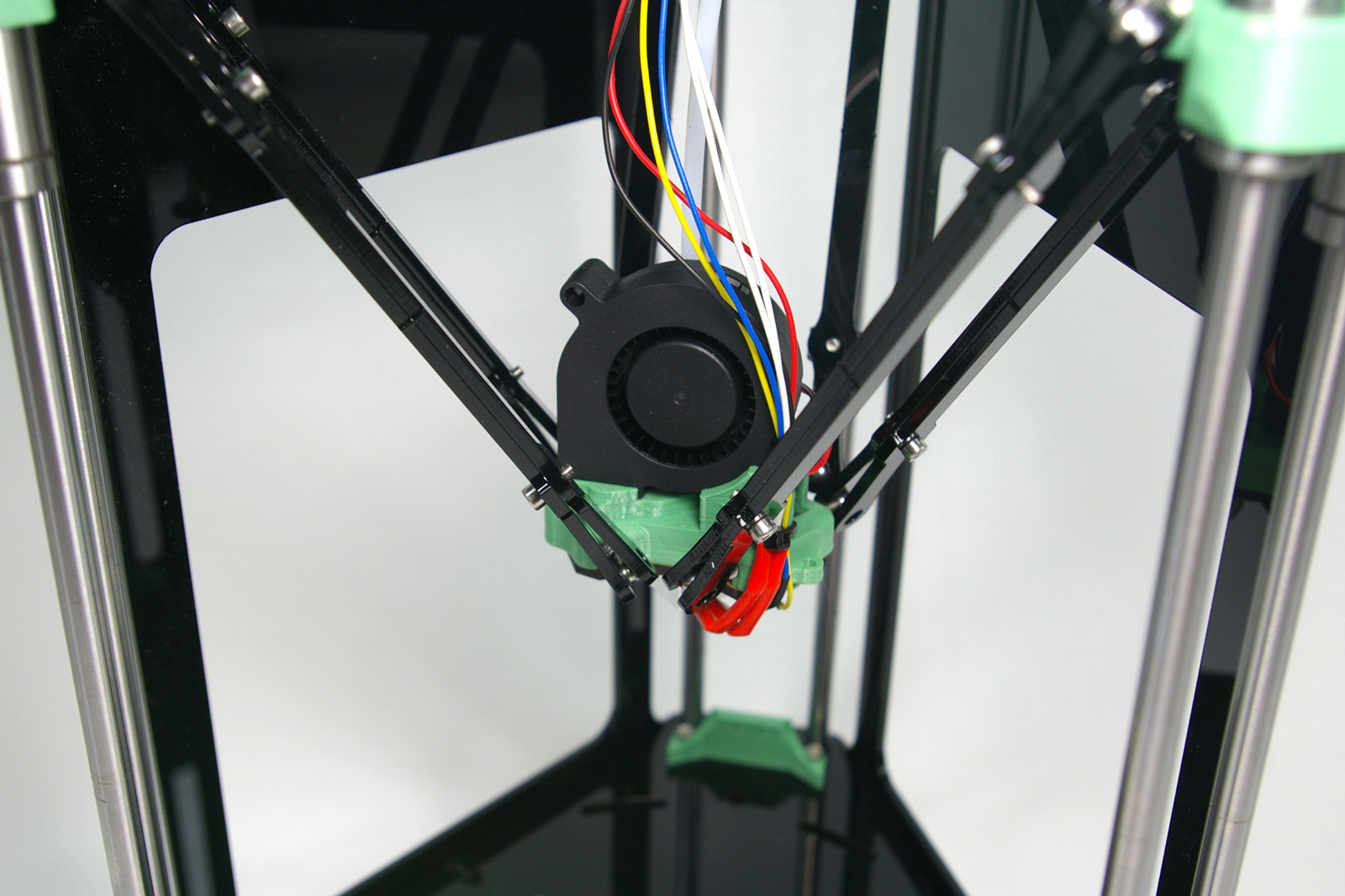
Mounting the effector
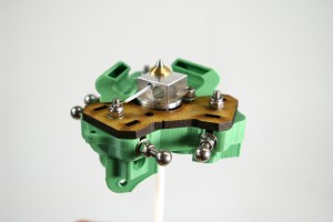
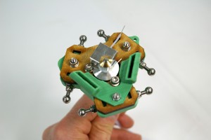
| Orientate the effector so the fan is facing the open side of the printer. As you did when connecting the rods to the carriages, gently prise the rod ends apart, and slip them over the balls of the effector. Tighten the grip of the rods on the stainless steel balls, by tightening the M3x8mm cap head screws on the rods. |
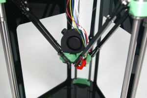 |
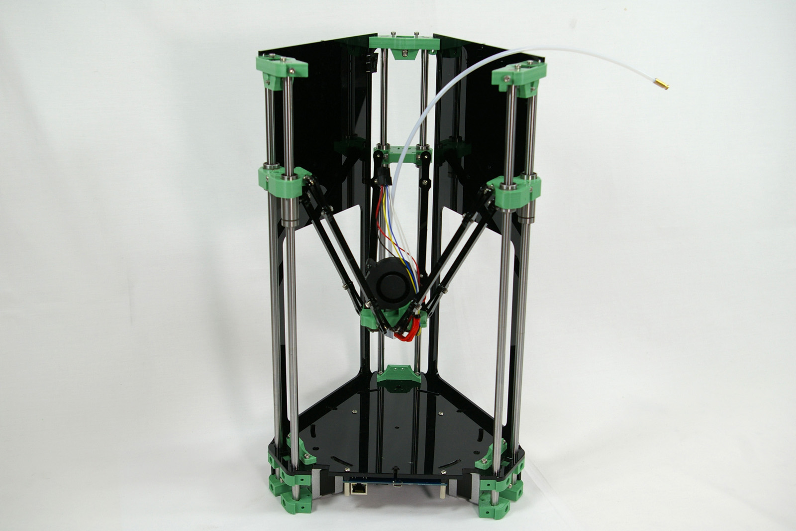
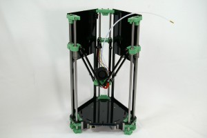
| The printer so far. |
|